Chapter 2: Arduino👩💻
- Rakshan Bathri
- Dec 8, 2024
- 13 min read
Chapter 2 Contents:
Chapter 2.1: Introduction
what's this blog about?

Hello👋
From the title of the blog, you can probably guess what this blog is about (hint: look at the picture 🖼️).
In this blog, I will be documenting my journey of creating TWO (not one but TWO ✌️) Arduino-related tasks, along with sharing with you guys my code 💻, how it works, and some challenges 😵 that I faced along the way❗
The two tasks that I will be covering today are:
Interfacing a Light-Dependent Resistor (LDR) 🌞➡️🌑
Interfacing 3 LEDs 💡💡💡
Chapter 2.2.1: Light-Dependent Resistor
sounds cool I guess

Light-Dependent Resistor (LDR)
Before I begin yapping, let me tell you how an LDR works. When the red swirly thing 🔴 is in contact with light 🌞, the resistance of that red swirly thingy decreases, which allows more current ⚡ to flow through. So, when there is more light 🌟, resistance decreases, and current increases, and vice versa.
Now let me tell you about my task 📋. I basically just need to connect an LDR to my Maker UNO board and use the Arduino IDE's Serial Monitor 🖥️ to read and display its signal 📊❗
Q: "Didn't we do this in secondary school❓ What's so hard about it❓ A: I forgot everything.
Chapter 2.2.2: Code and References
2nd hardest part
Coding Time!
(Honestly speaking, I thought this part would be hard but it actually was quite doable)
let me start by showing you my code for the task.
Code | Explanation |
void setup() { Serial.begin(9600); } void loop() { Serial.println(analogRead(A0)); delay(300); } | This is where I set things up. I’m starting the serial communication at 9600 baud. This part only runs once when the Arduino powers up or when I upload the code to the board. This is the main loop that keeps running. First, it reads the analog signal from pin A0. Then, it converts the signal into a digital value and it sends the value to the Serial Monitor. Finally, it pauses for 300 milliseconds before starting over as I didn't want my laptop to crash. |
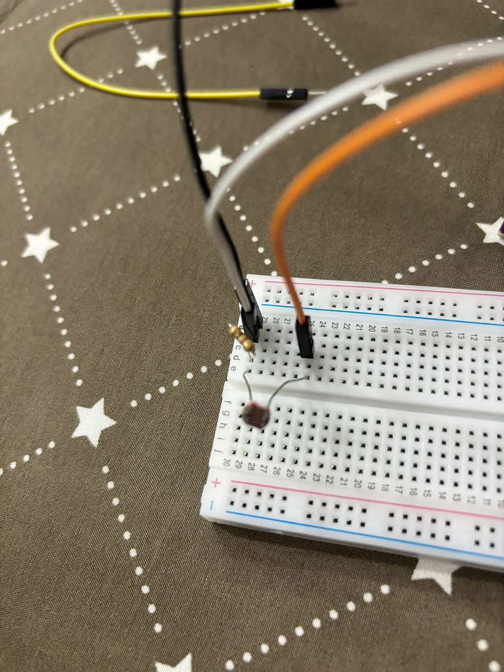
How did I connect it? First, I powered up ⚡ the breadboard by connecting a wire from the 5V supply 🔋 to it. Next, I added an LED 💡, an LDR, and finally a resistor.
I included the LED to see how the current ⚡ flowing through the circuit varies with light intensity 🌟. The LED's brightness ✨ varied according to how much light the LDR received, making it easier to visualise 👀 the circuit's response.
I also added the resistor because, without it, the LED would have been far too bright 🌟 and could have fused 💥❗ The resistor helps to regulate the current ⚡, keeping the LED safe while still responding to changes in light.
Of course, I didn’t know how to do it on the first try 🤦♂️, which is why I had to watch a quick YouTube video 📺 on how to connect things together. Then, when I got the gist of it, I tried to do it myself 💪❗
Chapter 2.2.3: Problems...
trial and error

Urgh.
You see that picture there? The LDR was receiving the brightest signal even though I wasn’t even doing anything 🤷♂️ to it. I was actually so confused 🤔 at this point because...Ok, I just thought it would work because it made sense 🧠, but in the end, it didn’t 🚫❗
So, remember when I said I would do the rest myself 💪 when I got the gist of it? Yeah, apparently I didn’t 😅, so I went to watch the video 📺 again and changed the orientation 🔄 of the wires and resistors.
Here’s the final product 🛠️ before I added my own personal touch ✨❗

It looks so boring right❓No lights or anything❗So... here's how I made it ✨unique✨
Here is my final product❗❗

To resolve the problem, I realised I needed to shift my A0 wire to another connection 🔄. It should be placed after the LDR, as this is where the signal 📶 is generated.
After I made that adjustment, the signal from the LDR was correctly routed to the A0 pin. Then I used the resistor to regulate the current⚡, allowing it to flow properly to the ground wire. This configuration ensured that the circuit worked as expected, with the LDR's light sensitivity 🌞 accurately reflected.
(This was the only problem I faced because the code was relatively simple compared to the next task...)
Chapter 2.2.4: Proof!
showcasing time
Here is what happens when I cover the LDR with my hand (this reduces the signal the LDR receives)
Here is what happens when I shine a torchlight onto the LDR (this increases the signal the LDR receives)
Before I show you the last clip, have you ever wondered why some lamps 💡 turn on automatically at night 🌙❓ It’s because they use an LDR❗ The LDR detects the light level, and when it gets dark, it triggers the lamp to turn on.
(I connected the LED the wrong way and I found this cooler instead.)
So, when there’s sunlight 🌞, the lamp turns off, but when it’s nighttime 🌙 (or no sunlight), the lamp turns on❗(Or in this case, the LED). This is all thanks to the LDR, which detects the light levels and automatically adjusts the lamp based on the surrounding brightness.
It’s a simple yet effective way to make sure your light only turns on when it’s needed🤓☝
(I used chatGPT for the last sentence because my English was not Englishing)
Chapter 2.3.1: LEDs
time for task 2!

Light-Emitting Diode (LED)
I think you know what an LED is by now. You see them almost everywhere❗ From the headlights of cars 🚗, the bus number indicator 🚌, and maybe even in your own room❗ Q: "I see them everywhere but how do they work❓ A: LEDs work by passing an electric current ⚡ through a special material, which then lights up 💡. The LED consists of two parts: the cathode (negative side)➖ and the anode (positive side) ➕. When current flows through, electrons ⚛️ move from the cathode to the anode, emitting energy in the form of light ✨. The colour of the light is determined by the material used inside the LED.
What distinguishes LEDs is that they use the majority of their energy for light, making them more energy efficient 💡 (which is good for UNSDG 7: Ensure access to affordable, reliable, sustainable, and modern energy for all 🌍) and lasting significantly longer than traditional light bulbs 💡 that you see on older cars 🚗 or homes 🏠.
Okay, that was long, time for the task to be done❗ This time, I had to Interface 3 LEDs (Red, Yellow, and Green) 🔴🟡🟢 to the Arduino board and program it to perform an action (fade or flash). I also have to be able to turn on and off the fading or flashing using a pushbutton 🔘. If you know me, of course I'm going to choose fading because it’s cooler and seems more challenging 💪. (I regret this 😂)
Okay, enough yapping, time for the code now 💻.
Chapter 2.3.2: Code and References
this was too hard.
Here's the code!
(Each sentence in the explanation corresponds to one line)
Code | Explanation |
bool isFading = false; bool lastButtonState = HIGH; void setup() { pinMode(2, INPUT_PULLUP); pinMode(9, OUTPUT); } void loop() { bool currentButtonState = digitalRead(2); if (currentButtonState == LOW && lastButtonState == HIGH) { isFading = !isFading; delay(50); } lastButtonState = currentButtonState; if (isFading) { for (int fadeValue = 0; fadeValue <= 255; fadeValue += 5) { analogWrite(9, fadeValue); delay(30); if (!isFading) break; } for (int fadeValue = 255; fadeValue >= 0; fadeValue -= 5) { analogWrite(9, fadeValue); delay(30); if (!isFading) break; } } else { analogWrite(9, 0); } } | Lines 1 and 2: This variable keeps track of whether the LED is fading or not. Starts off as false (not fading). This stores the last state of the button. It's set to HIGH because the button isn’t pressed yet. Setup: Sets pin 2 to read the button state. With the INPUT_PULLUP, the button will be HIGH when not pressed. Sets pin 9 to control the LED. It will send signals to make the LED light up. Pin 9 is used as it is a Pulse Width Modulation (PWM) pin that can vary its output signal instead of the standard ON/OFF. Loop: This reads the current state of the button and stores it in currentButtonState. Checks if the button has just been pressed (changes from not pressed to pressed). If the button was pressed, it toggles the isFading variable (turns fading on/off). Waits for 50 milliseconds to avoid multiple button presses being detected too quickly. Updates the lastButtonState to the current button state for the next loop. Fading Logic: If isFading is true, the LED will start fading in and out. Increases the brightness of the LED from 0 (off) to 255 (full brightness), by 5 each time. Sends the current brightness value to pin 9 to adjust the LED's brightness. Waits for 30 milliseconds before changing the brightness again. If the button is pressed again and isFading is set to false, the fading stops. Decreases the LED brightness back from 255 (bright) to 0 (off), in steps of 5. If isFading is false (fading is off), the LED will be turned off. Sets the LED brightness to 0 (off) when fading is not active. |
Did I figure this out by myself? NOPE. I needed a lot of help for this so I went to do some research on how to program a fading LED. Then I came across ❗THE❗ video.
Reference: How to Fade an LED with Arduino analogWrite
This video basically just told how the program works and the majority of the code was from a preexisting example that Arduino has for fading LEDs🤯
Why do I have some new codes that weren't taught in class? Well, I wanted the code to run forever when I pressed the button 🔘 once and stop when I pressed it again. It sounds easy to code and to be honest it is if you watch a video 📺. Reference: How to Program a Push Button with an Arduino
I managed to write the rough skeleton of the code and it kind of worked..❓It started when I pressed the button but didn't turn off 🔴, and I reallllyyyyy couldn’t find a reason why it did not work, so I went to the man's best friend, ChatGPT 🤖, which fixed the code by adding some other lines of code like "break" and more "if" lines.
How did I connect it?
This was honestly quite simple. I connected a wire from pin 9 to the breadboard, put the LED in series and connected the Ground wire at the output. Then, pressed the button❗

Here's a video of what it looks like❗
Chapter 2.3.3: Problems... (again)
wasn't it working? what's the issue now?
Is the code working? Yes
Is the task fulfilled? Yes
Am I satisfied? No
Can I do better? Yes
Am I going to do better? Yes
Here's the updated code!
(Each sentence in the explanation corresponds to one line)
Code | Explanation |
const int greenPin = 3; const int yellowPin = 5; const int redPin = 9; const int buttonPin = 2; bool isRunning = false; bool lastButtonState = HIGH; void setup() { pinMode(greenPin, OUTPUT); pinMode(yellowPin, OUTPUT); pinMode(redPin, OUTPUT); pinMode(buttonPin, INPUT_PULLUP); } void loop() { bool currentButtonState = digitalRead(buttonPin); if (currentButtonState == LOW && lastButtonState == HIGH) { isRunning = !isRunning; delay(50); } lastButtonState = currentButtonState; if (isRunning) { fadeLED(greenPin); fadeLED(yellowPin); fadeLED(redPin); } else { analogWrite(greenPin, 0); analogWrite(yellowPin, 0); analogWrite(redPin, 0); } } void fadeLED(int pin) { for (int brightness = 0; brightness <= 255; brightness += 10) { analogWrite(pin, brightness); delay(20); if (!isRunning) return; } for (int brightness = 255; brightness >= 0; brightness -= 10) { analogWrite(pin, brightness); delay(20); if (!isRunning) return; } } | Lines 1 to 6: Assigns pin 3 to the green LED. Assigns pin 5 to the yellow LED. Assigns pin 9 to the red LED. (Pin 3,5 and 9 are used as they are Pulse Width Modulation (PWM) pins that can vary their output signal instead of the standard ON/OFF.) Assigns pin 2 to the pushbutton. Keeps track of whether the LEDs are running a fading sequence. Starts off as false. Stores the last state of the button, starting as HIGH (button not pressed). Setup: Sets the green LED pin as an output. Sets the yellow LED pin as an output. Sets the red LED pin as an output. Configures the button pin with an internal pull-up resistor. Loop: Reads the current state of the button and stores it in currentButtonState. Checks if the button has just been pressed (state changes from HIGH to LOW). Toggles the isRunning variable to start or stop the LED sequence. Adds a delay to "unpress" the button press, avoiding multiple detections. Updates lastButtonState for the next loop. If isRunning is true, run the fading sequence for all three LEDs. Calls the fadeLED function for the green LED. Calls the fadeLED function for the yellow LED. Calls the fadeLED function for the red LED. If isRunning is false, turn off all LEDs. Turns off the green LED. Turns off the yellow LED. Turns off the red LED. Fading Logic: Gradually increases the LED brightness from 0 to 255 in steps of 10. Sets the brightness of the LED connected to the given pin. Waits 20 milliseconds before increasing the brightness again. Stops the fading sequence if the button is pressed again. Gradually decreases the LED brightness from 255 to 0 in steps of 10. Sets the brightness of the LED while fading out. Waits 20 milliseconds before decreasing the brightness again. Stops the fading sequence if the button is pressed again. |
Time for the fun part again (the connecting part)

Here's a preview of my setup so it's easier to visualise.
I connected each wire according to the corresponding LED bulb 💡. (So a wire from pin 9 to the red one 🔴 and pin 3 to the green one 🟢, etc.)
After that, I added a return pathway by using a resistor which also prevents the LED from fusing 💥. Yeah, I did the same for all of them and that's pretty much it.
BUT, what if, instead of a resistor, we used another electronic thingy to replace it? (Hint: I did that and I'll show you in the next section 📚)
Chapter 2.3.4: Final Product!
are we finally done omg omg

I removed the resistors for the green LED and added a resistor to the yellow and red LED only because they shined brighter after a few of my test runs and the green was too dim even without any resistance.

Here's the top view :)
SO FINALLYYYYYY, HERE IS THE FINAL PRODUCT❗❗
it looks so magnificent.
Chapter 2.4: Reflection
final stretch
As always, I like to keep my reflections more on the formal side so no more bolded words or emojis or whatever. In my opinion, I think that the Arduino activities are a good gateway for us Chemical Engineering students to explore other branches of engineering as well. For example, learning to code with Arduino is often the first step towards mastering other programming languages such as Python, which is widely used in courses related to Electrical and Electronic Engineering (EEE) like Computer Engineering or even Computer Science. As Chemical Engineers, we tend to focus on process design and systems, but understanding basic coding and the underlying principles of electronics opens up a new dimension of problem-solving and technical capabilities. Not only does it provide a seamless bridge to other engineering disciplines, but it also introduces me to an entirely new area of learning, one that encourages creativity and hands-on experimentation. For example, I could design a simple prototype like a night light that automatically turns on when the surrounding light is low, which would be a practical and interesting project in itself.
I believe the reason we have this lesson is not only to help us build our chemical product but also to develop a broader range of technical skills. Why? Because Chemical Engineering is a vast field, and there are many different areas of specialisation. For instance, a chemical engineer can work in industries like pharmaceuticals or explore completely different fields, such as Nanotechnology. The key takeaway is that beyond mastering concepts like Separation Processes, it's important to develop other technical skills that can complement our knowledge.
After completing the given tasks, I realised that if I had the chance to go back to Practical 2, where we had to simulate the movement of a shark's jaws, I would feel much more confident in handling the coding aspect, which could have made a significant contribution to my group's efficiency. Unfortunately, I can't go back, but I can apply the skills I’ve learned to my current project which is developing a Gas Detector for our chemical product.
One important lesson I’ve learned is that there are countless ways to approach a task. I came to this realisation after reading through my peers' blogs, where I saw that some of their code was more intricate, while others were simpler but still effective. This diversity in coding styles has given me a clearer understanding of how different people approach problem-solving. For example, some prefer concise and straightforward solutions, while others strive to make their code as flawless as possible. Lastly, a key takeaway from this experience, similar to my previous blog, is that I’m still a beginner when it comes to Arduino. How do I know this? Because there are so many Arduino templates I haven’t explored yet, which highlights the immense amount of knowledge still to be discovered. Despite the challenges, I truly enjoyed the coding process, and I might even explore coding further in my free time. I’m also considering pursuing a coding-related minor when I get to university, though it's still too early to make any final decisions. That's all.
That's the end of my blog, BYEBYE!


Comments